Fillet welds are probably the most common type of weld particularly in structural steel work applications so this first section will look at some of the design considerations of fillet welds. Designing Fillet Welds for Skewed T-Joints Part 1 Lessons Learned in the Field.
2
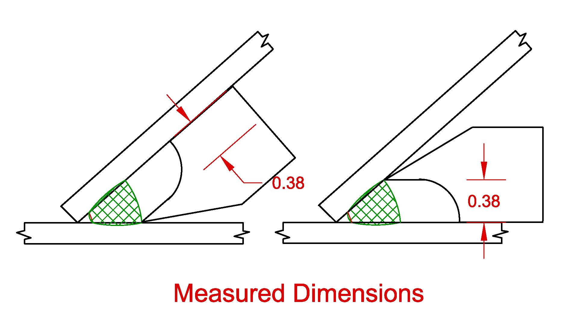
The present invention comprises a gauge for measuring certain dimensions of welds at skewed T joints the gauge being broadly denoted by the numeral 10.
. Eurocode 1993-1-82005 gives a designer a choice between two methods for the design of fillet welds. Detailing fillet welds for 90-degree T-joints is a fairly straightforward activityTake the 90-degree T-joint and skew itthat is rotate the upright member so as to create an acute and obtuse orientation and the resultant geometry of the fillet welds becomes more complicated see Figure 1The greater the degree of rotation the greater the differ-. However many designers are unaware of the AWS D11 skewed t-joint requirements and apply typical 90.
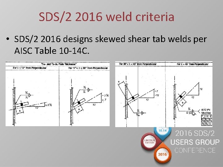
The American Welding Society Structural Welding Code - Steel AWS D11 provides design and detailing requirements for skewed t-joints. They may be used to make T lap and corner joints Fig4. Single-sided fillet welded joint types.
A series of equations can be used to. The American Welding Society Structural Welding Code - Steel AWS D11 provides design and detailing requirements for skewed t-joints. However many designers are unaware of the AWS D11 skewed t-joint requirements and apply typical 90.
For angles between 60 and 80 degrees the designer has to account for the effective throat using the formula contained in Annex B D11. Typical welds capable of being measured with gauge 10 are welds 12 and 14 shown in FIGS. Notice that the far side weld is less than the 5 16-in.
Depending on the skewed t-joint geometry designers are required to define the required weld leg or effective throat size. The effective throat shall be the shortest distance from the joint root to the weld face of the diagrammatic weld see Annex I. Other welds include partial penetration groove welds.
24 Fillet Welds 241 Effective Throat 2411 Calculation. A weld preparation the weld prep is therefore. 2336 Minimum Skewed T-Joint Weld Size.
2337 Effective Throat of Skewed T-Joints. A tabulation of mea-. The simplified and the directional methods.
Depending on the skewed t. Fillet Weld The required fillet welds are shown in Figure 8. Engineers and designers have been alerted to the AISCAWS requirements for limiting angles for skewed T-joints.
Used to calculate the required fillet weld size for the far side weld. Download Citation Designing fillet welds for skewed T-joints - Part 1 Detailing fillet welds for 90-degree T-joints is a straightforward activity. Consider the Transfer of Stress through Members Welding Innovation Vol.
Oenoral Construction Specification O-29C has been revised to clarity. The term fillet weld is applicable to welds deposited on the joint with dihedral angles between 80 and 100 degrees. See Annex II for formula governing the calculation of effective throats for fillet welds in skewed T-joints.
The American Welding Society Structural Welding Code - Steel AWS D11 provides design and detailing requirements for skewed t-joints. If the dihedral angle is less than 80 or more than 100 degrees it is a welded skewed T-joint. There is no specific guidance on which method to use and in practice the choice is usually made on practical grounds.
W 1 20221 in. Method of Analysis Figure 1 shows the logic flow of the analysis used in this study. Depending on the skewed t-joint geometry designers are required to define the required weld leg or effective throat size.
The requirements of 2328 shall apply. A thin section of a double fillet-welded T-joint speci- men was removed from a long joint sam- ple and the analysis was conducted on. In the directional method the force acting on the fillet weld is resolved into components parallel and.
Skewed T-joint fillet welds have either been qualified by analysis andor testing or are considered nonload carrying welds. 2 To provide some guidance for effi- cient design of fillet welds. The effective throat of a skewed T-joint in angles between 60 and 30 shall be the minimum distance from the root to the diagrammatic face.
Fillet weld that is. In order to weld the full thickness of a plate and achieve the weld throat thickness required by design it is therefore necessary to cut away sufficient metal along the joint line so that the welding electrode has access to the root of the joint enabling the root pass to be deposited and then the remainder filled to complete the joint. No reduction shall be assumed in design calculations to allow for the start or stop of the weld.
Fillet weld size shown in Table 10-14C on page 10-177. Sin 682 0 0247 in.

Typical Weld Joints
2

The Skew T Fillet Weld Gauge By Gal Gage Company Youtube
2
Skewed T Joints Between 60 And 30 Degrees
2
Skewed Shear Tab Welding How Sds2 Designs Shear

Nstx Supported By Nstx Centerstack Upgrade Project Meeting P Titus March American Welding Society Stainless Steel Edition Ppt Download
0 comments
Post a Comment